Saturday, January 24, 2015

Orbital Aero Model: Vector Model

** Update 21 Jan 2017: This Vector class has been deprecated, new version posted here. **

I created a Vector class that is used extensively in the code. Absolute locations, relative locations, velocities, accelerations, and forces all use this same class to hold values in 3 dimensional space. My vector is a simple 1 dimensional array of 3 values. Using an array makes things easier when dealing with matrix math (which will be introduced later). Also keeping it generic means those values could be considered an x/y/z or phi/theta/psi (orientation).

Operator Overloading


Operator overloading allows the programmer to use standard math operators on structures or classes that the compiler would normally not know what to do with. I use them extensively with vectors in the Orbital Aero Model; it helps to both condense the code and make it more readable.

For example, I'm trying to add vectors b and c together to store them in a.

Instead of writing code such as:
a.x = b.x + c.x;
a.y = b.y + c.y;
a.z = b.z + c.z;

I could write:
a = b + c;

The overload for that case would be:
Vector Vector::operator+(const Vector &vectorToAdd)
{
return Vector(this->value[0] + vectorToAdd.value[0], this->value[1] + vectorToAdd.value[1], this->value[2] + vectorToAdd.value[2]);
}

The addition operation is being performed on vector b (this) and vector c (vectorToAdd). It is returning a new vector of the sum that is stored in a.

A similar example is to add the value of b into a.

Instead of writing code such as:
a.x += b.x;
a.y += b.y;
a.z += b.z;

I could write:
a += b;

The overload for that case would be:
Vector &Vector::operator+=(const Vector &vectorToAdd)
{
this->value[0] += vectorToAdd.value[0];
this->value[1] += vectorToAdd.value[1];
this->value[2] += vectorToAdd.value[2];
return *this;
}

The addition operation is being performed on vector a (this) and vector b (vectorToAdd). The summed value is stored directly in a.

Since so much of the code uses my vector class that has operator overloading, I figured it would be best to share that class first. As I extend the functionality of my vector math, I'll update this post to include the latest additions.

More Resources


For more information on vector math, I recommend learning the following concepts:
Vector
Dot Product
Cross Product

If you've never seen a Dot Product or Cross Product before, you may be questioning what they're for. They're actually both VERY important concepts when doing 3-dimensional math. You'll see examples of them in action in the code that follows.

VectorModel.h


#pragma once

class Vector
{
private:

public:
double value[3];

Vector();

Vector(double value0, double value1, double value2);

Vector &Vector::operator=(double newValue);

Vector &Vector::operator=(const Vector &thatVector);

Vector Vector::operator-();

Vector Vector::operator+(const Vector &vectorToAdd);

Vector Vector::operator-(const Vector &vectorToSubtract);

Vector Vector::operator*(double valueToMultiply);

Vector Vector::operator*(const Vector &vectorToMultiply);

Vector Vector::operator/(double valueToDivide);

Vector &Vector::operator+=(const Vector &vectorToAdd);

Vector &Vector::operator-=(const Vector &vectorToSubtract);

Vector &Vector::operator*=(double valueToMultiply);

Vector &Vector::operator/=(double valueToDivide);

double magnitude();

Vector unit();

Vector sign();

static double dotProduct(Vector vector1, Vector vector2);
};


VectorModel.c


#include "math.h"
#include "VectorModel.h"

Vector::Vector()
{
this->value[0] = 0.0;
this->value[1] = 0.0;
this->value[2] = 0.0;
return;
}

Vector::Vector(double value0, double value1, double value2)
{
this->value[0] = value0;
this->value[1] = value1;
this->value[2] = value2;
return;
}

Vector &Vector::operator=(double newValue)
{
this->value[0] = newValue;
this->value[1] = newValue;
this->value[2] = newValue;
return *this;
}

Vector &Vector::operator=(const Vector &thatVector)
{
// Protect against self-assignment. (Otherwise bad things happen when it's reading from memory it has cleared.)
if (this != &thatVector)
{
this->value[0] = thatVector.value[0];
this->value[1] = thatVector.value[1];
this->value[2] = thatVector.value[2];
}
return *this;
}

Vector Vector::operator-()
{
return Vector(-this->value[0], -this->value[1], -this->value[2]);
}

Vector Vector::operator+(const Vector &vectorToAdd)
{
return Vector(this->value[0] + vectorToAdd.value[0], this->value[1] + vectorToAdd.value[1], this->value[2] + vectorToAdd.value[2]);
}

Vector Vector::operator-(const Vector &vectorToSubtract)
{
return Vector(this->value[0] - vectorToSubtract.value[0], this->value[1] - vectorToSubtract.value[1], this->value[2] - vectorToSubtract.value[2]);
}

Vector Vector::operator*(double valueToMultiply)
{
return Vector(this->value[0] * valueToMultiply, this->value[1] * valueToMultiply, this->value[2] * valueToMultiply);
}

Vector Vector::operator*(const Vector &vectorToMultiply)
{
return Vector(this->value[0] * vectorToMultiply.value[0], this->value[1] * vectorToMultiply.value[1], this->value[2] * vectorToMultiply.value[2]);
}

Vector Vector::operator/(double valueToDivide)
{
return Vector(this->value[0] / valueToDivide, this->value[1] / valueToDivide, this->value[2] / valueToDivide);
}

Vector &Vector::operator+=(const Vector &vectorToAdd)
{
this->value[0] += vectorToAdd.value[0];
this->value[1] += vectorToAdd.value[1];
this->value[2] += vectorToAdd.value[2];
return *this;
}

Vector &Vector::operator-=(const Vector &vectorToSubtract)
{
this->value[0] -= vectorToSubtract.value[0];
this->value[1] -= vectorToSubtract.value[1];
this->value[2] -= vectorToSubtract.value[2];
return *this;
}

Vector &Vector::operator*=(double valueToMultiply)
{
this->value[0] *= valueToMultiply;
this->value[1] *= valueToMultiply;
this->value[2] *= valueToMultiply;
return *this;
}

Vector &Vector::operator/=(double valueToDivide)
{
this->value[0] /= valueToDivide;
this->value[1] /= valueToDivide;
this->value[2] /= valueToDivide;
return *this;
}

double Vector::magnitude()
{
return sqrt( (this->value[0] * this->value[0]) + (this->value[1] * this->value[1]) + (this->value[2] * this->value[2]) );
}

Vector Vector::unit()
{
double mag = magnitude();
Vector unitVector;
unitVector.value[0] = this->value[0] / mag;
unitVector.value[1] = this->value[1] / mag;
unitVector.value[2] = this->value[2] / mag;
return unitVector;
}

Vector Vector::sign()
{
Vector signVector;
signVector.value[0] = sgn(this->value[0]);
signVector.value[1] = sgn(this->value[1]);
signVector.value[2] = sgn(this->value[2]);
return signVector;
}

double Vector::dotProduct(Vector vector1, Vector vector2)
{
return ((vector1.value[0] * vector2.value[0]) + (vector1.value[1] * vector2.value[1]) + (vector1.value[2] * vector2.value[2]));
}


Copyright (c) 2015 Clinton Kam
Permission is hereby granted, free of charge, to any person obtaining a copy of this software and associated documentation files (the "Software"), to deal in the Software without restriction, including without limitation the rights to use, copy, modify, merge, publish, distribute, sublicense, and/or sell copies of the Software, and to permit persons to whom the Software is furnished to do so, subject to the following conditions:
The above copyright notice and this permission notice shall be included in all copies or substantial portions of the Software.
THE SOFTWARE IS PROVIDED "AS IS", WITHOUT WARRANTY OF ANY KIND, EXPRESS OR IMPLIED, INCLUDING BUT NOT LIMITED TO THE WARRANTIES OF MERCHANTABILITY, FITNESS FOR A PARTICULAR PURPOSE AND NONINFRINGEMENT. IN NO EVENT SHALL THE AUTHORS OR COPYRIGHT HOLDERS BE LIABLE FOR ANY CLAIM, DAMAGES OR OTHER LIABILITY, WHETHER IN AN ACTION OF CONTRACT, TORT OR OTHERWISE, ARISING FROM, OUT OF OR IN CONNECTION WITH THE SOFTWARE OR THE USE OR OTHER DEALINGS IN THE SOFTWARE.

Thursday, January 22, 2015

Orbital Aero Model: Intro

Back in college (a little over a decade ago), I made an orbital mechanics / space simulation into a MUD (Multi User Dungeon / Multi User Dimension). I used SocketMUD as a base and added in the concept of "bodies" that interact with each other. The bodies would pull on one another with their gravity (based on mass) and could bounce off each other (based on mass and coefficient of restitution). There was also a simple implementation of electromagnetic waves that could originate from a body and propagate through space to impact other bodies (secondary bodies would cause shadows in the electromagnetic wave).

I think I had the sun, planets, Earth's moon, and a couple spacecraft in continuous motion (real time). Users could log in, look at positions and velocities of the bodies, create new bodies, and delete existing bodies. For the year or so I had the MUD running, I think I had one other person log in and play around with the simulation. So I can't say it was the most popular, but most of the time MUDs are meant for killing goblins and leveling up - not watching x/y/z coordinates change.

The original code worked for what it was, but you can learn a lot about coding techniques in 10 years. So this past year I've been dusting off the old stuff and bringing it back to life. It's no longer a MUD, but I do have a simple visualizer...


In this video you can see several spacecraft orbiting the Earth (currently a perfect sphere, but that will change too). The spacecraft nearest to the Earth are actually being dragged down because they're within the Earth's atmosphere. Later in the video you can see a spacecraft orbiting the moon which is orbiting the Earth. I find the history trails of the spacecraft orbiting the moon to be very interesting.

Why call it Orbital Aero?


I want to continue to build as realistic simulation as possible for vehicles travelling on planets, through the atmosphere of planets, and through space. Hence orbital for space and aero for atmospheric effects near a planet. The goal would be to accurately simulate a spacecraft taking off from the Earth, travelling through space, and landing on Mars. (Or to a planet in another solar system!)

80% Solution


I'm developing based on what I'll call the "80% solution". To get near a 100% accurate simulation is extremely expensive (both in development hours and CPU clock cycles). However, to get an 80% accurate simulation isn't nearly as difficult and usually suffices for most customers needs. (Obviously what is "80%" is very subjective.)

I'm going to tackle one concept of the simulation and get it to what I consider 80%, then move on to the next concept. As I go around on the different parts of the simulation (atmospheric modeling or physical shapes of bodies), I'll revisit previous code and essentially redefine 80%.

For example: Right now every body in the simulation is a perfect sphere. To have basic spacecraft orbit a planet, transfer between planets, or escape the solar system, it's good enough. That's what the simulation can do now. However to do interactions between spacecraft and a planet (GPS modeling for example), it's important to have an ellipsoid shape Earth (such as the WGS-84 model). So when the goal is to do GPS, what suffices for 80% is redefined and work will have to be completed to reach that point. To further this point, a WGS-84 round Earth model will suffice for many requirements, but if you're trying to drive a car on the surface of a planet its woefully inadequate. At that point you'll need to load some kind of elevation data such as SRTM (Shuttle RADAR Topology Mission) or DTED (Digital Terrain Elevation Data).

A little background on myself... I got my degree in Aerospace Engineering and have been working on simulation software professionally ever since. This is another long term project. I'll be posting updates on the simulation and the physics behind it as it progresses. If you have questions, comments, suggestions for improvements, or reports of errors then please let me know! (Side note, the Arduino computer is still in the works. I said I've got too many projects!)

Saturday, January 3, 2015

Arduino Retro Computer: Second Joystick

I've been able to build and wire up my second joystick!


Learning some lessons from the first version, I did redesign the lid so it fits better into the case. Rather than the prongs in the corners, the lid now has 4 tabs along the top and bottom of the joystick. I can drill holes through the joystick case and into the tabs to add a set screw to keep the lid in position (in the picture above you can see a set screw at the top left and bottom right of each controller).


The guts of the two controllers...


I printed a new lid for the first joystick as well so they're the same. The wiring inside the two controllers are identical. I did change the pin layout at the Arduino for joystick #1 so it would be grouped with joystick #2. My new pin layout:

const int Joystick1SelectPin = 40;
const int Joystick1RightPin = 41;
const int Joystick1TopPin = 42;
const int Joystick1LeftPin = 43;
const int Joystick1BottomPin = 44;
const int Joystick1AnalogX = 0; // Analog 0
const int Joystick1AnalogY = 1; // Analog 1

const int Joystick2SelectPin = 45;
const int Joystick2RightPin = 46;
const int Joystick2TopPin = 47;
const int Joystick2LeftPin = 48;
const int Joystick2BottomPin = 49;
const int Joystick2AnalogX = 2; // Analog 2
const int Joystick2AnalogY = 3; // Analog 3


Initializing my joysticks with the Joystick Class (described in the previous post):

  joysticks[0].init(Joystick1SelectPin, Joystick1RightPin, Joystick1TopPin, 
                    Joystick1LeftPin, Joystick1BottomPin, Joystick1AnalogX, Joystick1AnalogY);
  joysticks[1].init(Joystick2SelectPin, Joystick2RightPin, Joystick2TopPin, 
                    Joystick2LeftPin, Joystick2BottomPin, Joystick2AnalogX, Joystick2AnalogY);

And of course someone became very interested while I was doing the final wiring.


Thursday, December 25, 2014

Arduino Retro Computer: Joystick Interface

The joystick itself contains no logic - it's just push buttons and potentiometers. The brains of the input reside in the Arduino.

Some very good references on how to read analog and digital input on the Arduino:

http://arduino.cc/en/Tutorial/ReadAnalogVoltage
http://arduino.cc/en/tutorial/button
http://arduino.cc/en/Reference/Constants

Basically, we can't just wire from 5V through a push button then to the data input pin; we must use a pull-up (or pull-down) resistor. The critical piece for the push buttons from those references is as follows: "If you have your pin configured as an INPUT, and are reading a switch, when the switch is in the open state the input pin will be "floating", resulting in unpredictable results. In order to assure a proper reading when the switch is open, a pull-up or pull-down resistor must be used. The purpose of this resistor is to pull the pin to a known state when the switch is open. A 10 K ohm resistor is usually chosen, as it is a low enough value to reliably prevent a floating input, and at the same time a high enough value to not not draw too much current when the switch is closed."

Hardware

9-Position Female D-Sub Connector (Radio Shack #276-1538)
5x 10k Ohm Resistor
Breadboard

Wiring

The wiring for the select button is different than the 4 push buttons. The Joystick Breakout Board shorts Select (S1) to GND when the stick is pressed in. To read this, Select is wired with a pull-up resistor while the others are with pull-down.

Wiring Schematic:

Created with http://www.digikey.com/schemeit

The pin layout for the serial cable is as follows:

#1 S1 (Stick Select Button)
#2 S2 (Right Button)
#3 S3 (Top Button)
#4 S4 (Left Button)
#5 S5 (Bottom Button)
#6 Vcc
#7 Analog Xout
#8 Analog Yout
#9 GND


Code

I created a Joystick Class in my operating system code to ease in interfacing:
class JoystickModel
{
  private:
  int buttonPinSelect;
  int buttonPinRight;
  int buttonPinTop;
  int buttonPinLeft;
  int buttonPinBottom;
  int analogPinX;
  int analogPinY;

  public:
  bool init(int newButtonPinSelect, int newButtonPinRight, int newButtonPinTop, int newButtonPinLeft, int newButtonPinBottom,
            int newAnalogPinX, int newAnalogPinY)
  {
    buttonPinSelect = newButtonPinSelect;
    buttonPinRight = newButtonPinRight;
    buttonPinTop = newButtonPinTop;
    buttonPinLeft = newButtonPinLeft;
    buttonPinBottom = newButtonPinBottom;
    
    pinMode(buttonPinSelect, INPUT);
    pinMode(buttonPinRight, INPUT);
    pinMode(buttonPinTop, INPUT);
    pinMode(buttonPinLeft, INPUT);
    pinMode(buttonPinBottom, INPUT);

    analogPinX = newAnalogPinX;
    analogPinY = newAnalogPinY;
       
    return true;
  }
  
  bool selectPressed()
  {
    // Returns true if button is pressed.
    // Select button uses LOW because the joystick breakout shorts to ground with select.
    return (digitalRead(buttonPinSelect) == LOW);
  }
  
  bool leftPressed()
  {
    // Returns true if button is pressed.
    return (digitalRead(buttonPinLeft) == HIGH);
  }
  
  bool topPressed()
  {
    // Returns true if button is pressed.
    return (digitalRead(buttonPinTop) == HIGH);
  }
  
  bool rightPressed()
  {
    // Returns true if button is pressed.
    return (digitalRead(buttonPinRight) == HIGH);
  }
  
  bool bottomPressed()
  {
    // Returns true if button is pressed.
    return (digitalRead(buttonPinBottom) == HIGH);
  }
  
  float analogX()
  {
    // Returns position of stick between -1 and 1.
    // Take - as X potentiometer is mounted reversed on controller.
    return -(((float)analogRead(analogPinX) / 512.0) - 1.0);
  }
  
  float analogY()
  {
    // Returns position of stick between -1 and 1.
    // Take - as Y potentiometer is mounted reversed on controller.
    return -(((float)analogRead(analogPinY) / 512.0) - 1.0);
  }
};

Global:
const int Joystick1SelectPin = 3;
const int Joystick1RightPin = 4;
const int Joystick1TopPin = 5;
const int Joystick1LeftPin = 6;
const int Joystick1BottomPin = 7;
const int Joystick1AnalogX = 0;
const int Joystick1AnalogY = 1;

const byte numberOfJoysticks = 2;
JoystickModel joysticks[numberOfJoysticks];

Inside setup():
  joysticks[0].init(Joystick1SelectPin, Joystick1RightPin, Joystick1TopPin, 
                    Joystick1LeftPin, Joystick1BottomPin, Joystick1AnalogX, Joystick1AnalogY);

Inside loop():
  float analogX = joysticks[0].analogX();
  float analogY = joysticks[0].analogY();
  char analogXString[10];
  char analogYString[10];
  dtostrf(analogX, 5, 3, analogXString);
  dtostrf(analogY, 5, 3, analogYString);
  Serial.print("Analog X: ");
  Serial.print(analogXString);
  Serial.print(" Analog Y: ");
  Serial.print(analogYString);

  if (joysticks[0].selectPressed())
  {
    Serial.print(" Select Pressed");
  }
  if (joysticks[0].rightPressed())
  {
    Serial.print(" Right Pressed");
  }
  if (joysticks[0].topPressed())
  {
    Serial.print(" Top Pressed");
  }
  if (joysticks[0].leftPressed())
  {
    Serial.print(" Left Pressed");
  }
  if (joysticks[0].bottomPressed())
  {
    Serial.print(" Bottom Pressed");
  }
  Serial.println("");


Output from the console:


Asteroids + Controller


I wanted to play the Asteroids game with my new controller, so I made the following changes to the game code to get it to work:

Replaced controller_init() with:
static void controller_init()
{
  // Configure input pins with internal pullups
  pinMode(6, INPUT);
  pinMode(7, INPUT);
}

Replaced controller_sense() with:
static byte controller_sense(uint16_t clock)
{
  byte r = 0;
  if (digitalRead(6))
  {
    r |= CONTROL_UP;
  }
  if (digitalRead(7))
  {
    r |= CONTROL_DOWN;
  }
  return r;
}

In static void handle_player(byte i, byte state, uint16_t clock), there is a line:
    char rotate = (512 - analogRead(0)) / 400;
Since my stick is reversed, I just had to make that negative:
    char rotate = -(512 - analogRead(0)) / 400;


Copyright (c) 2015 Clinton Kam
Permission is hereby granted, free of charge, to any person obtaining a copy of this software and associated documentation files (the "Software"), to deal in the Software without restriction, including without limitation the rights to use, copy, modify, merge, publish, distribute, sublicense, and/or sell copies of the Software, and to permit persons to whom the Software is furnished to do so, subject to the following conditions:
The above copyright notice and this permission notice shall be included in all copies or substantial portions of the Software.
THE SOFTWARE IS PROVIDED "AS IS", WITHOUT WARRANTY OF ANY KIND, EXPRESS OR IMPLIED, INCLUDING BUT NOT LIMITED TO THE WARRANTIES OF MERCHANTABILITY, FITNESS FOR A PARTICULAR PURPOSE AND NONINFRINGEMENT. IN NO EVENT SHALL THE AUTHORS OR COPYRIGHT HOLDERS BE LIABLE FOR ANY CLAIM, DAMAGES OR OTHER LIABILITY, WHETHER IN AN ACTION OF CONTRACT, TORT OR OTHERWISE, ARISING FROM, OUT OF OR IN CONNECTION WITH THE SOFTWARE OR THE USE OR OTHER DEALINGS IN THE SOFTWARE.

Saturday, December 20, 2014

Arduino Retro Computer: Joystick Construction

Common in the older connect-to-your-television computers were joysticks. After all, those computers were really for playing games (yes, they were advertised as "educational" or for "work", but my TI-99/4A has built in joystick ports for a reason). The Asteroids game included in the Gameduino definitely convinced me I needed joysticks. Yes I could retrofit a classic Nintendo controller, or... I could build one from scratch.

Hardware:

Dual Printed Circuit Board (Radio Shack #276-148)
Round Tact Buttons (Adafruit #1009)
Joystick Breakout Board (Adafruit #512)
9-Position Male D-Sub Connector (Radio Shack #276-1537)
6' Serial Cable (Radio Shack #26-1402)
#4-40 x 3/8" Bolts
#4-40 x 1/2" Bolts
#6 Washers

Creating the Case:

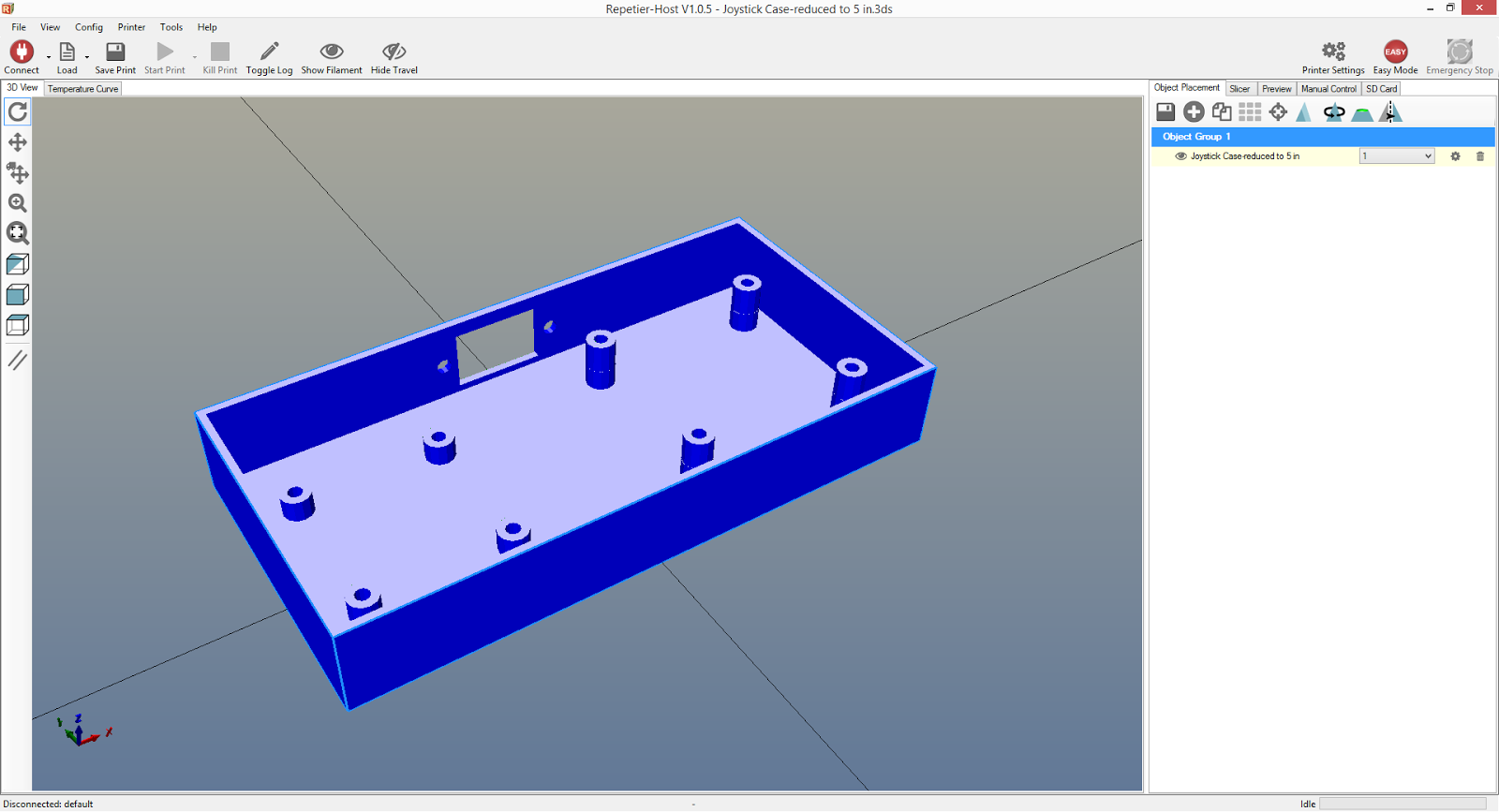
I used Sketch Up to create a case. The case includes extruded mounts for the two boards and an opening for the serial connector:


The lid for the case:


The extrusions at the 4 corners of the lid are so it doesn't have any play room to rotate or slide around the case. The extrusion in the middle is so I can put a set screw to secure the lid onto the case. It is opposite of the serial cable connection.

I used Repetier / Slic3r to create the G-code of my case:


3 hours 4 minutes later I had my printed case!


Well, one more hour for the lid.


(There are all sorts of tips and tricks out there on how to get the first layer to stick to the print surface. I've found double sided tape to work very well. It's cheap and it easily comes off the finished part.)

I basically had to monitor the print for the entire 4 hours, someone is very interested in the printer...


Wiring:

The brains of the joystick will be with the Arduino. The joystick itself is basically just a collection of buttons and potentiometers wired to a serial cable.

Wiring Schematic:


The pin layout for the serial cable is as follows:

#1 S1 (Stick Select Button)
#2 S2 (Right Button)
#3 S3 (Top Button)
#4 S4 (Left Button)
#5 S5 (Bottom Button)
#6 Vcc
#7 Analog Xout
#8 Analog Yout
#9 GND

I wired the Vcc from the D-Sub connector to the button board - then I jumped the Vcc from the button board to the analog stick board. This helped keep the wire area around the connector clean and simple. Photo of the back so that makes sense...


In the photo above you can see the Vcc long bare wire that makes connections across all the buttons.

The final product!

Lid off:


Lid on:


I was expecting to needs nuts for the mounting bolts, so I designed the case with the holes going all the way through. However I've found the #4 bolts fit snugly in the 1/8" diameter holes and no nuts were necessary. I did need a few washers for the bolts on the analog stick board as the 3/8" length bolts were too long and would protrude out (I suppose I could have found shorter bolts or dremeled the bolts in half, but washers were easier.)


The bottom turned out nice and flat.

Lessons Learned:

The case came out pretty well, but there are a couple items that could be improved upon:

#1 Probably the most significant change needed is the analog stick. When in the neutral position it looks great, but as the stick tilts you can see behind the analog's cone cover. To prevent that, I need to have the overall case be thicker so I can put the lid higher over the analog stick. With the lid higher, I'd be able to use a smaller hole that closes around the analog stick's cone cover. Then as the stick tilts you wouldn't be able to look inside the case. I'd rather not have the controller be any bulkier though and really that's getting pretty nit-picky. For my purposes it's not a big deal.

#2 I could have gone a bit fancier with how the lid fits onto the case. Maybe cut some gaps in the case that the lid notches / snaps into? I'll think about it. The lid fits a bit tight right now. I need to give the lid's extrusions probably 1/16" or 1/32" clearance from the edges of the case so it fits in better and doesn't try to bow out.

This is just the first joystick; I've purchased enough parts to build a second for multiplayer. I'll give this first one some use and think about more tweaks before I construct the second.

Next up, the joystick wiring at the Arduino!

Saturday, December 13, 2014

Arduino Retro Computer: PS/2 Keyboard

Now that I had a video output, I needed some method of input to the computer. I have an extra PS/2 keyboard, and Adafruit sells a very handy PS/2 Wired Connector (Part #804)!


The wires coming from the PS/2 connector are flexible, so I soldered some rigid pins that can plug into the Arduino's GPIO slots.

Wiring from the PS/2 connector to Arduino Mega:
Black to GND
Green to 5V
Yellow to 2 (PWM, IRQ pin)
Brown to 30 (Digital, Data pin)
White - not used
Red - not used


Next up was the code. The Arduino PS/2 library and more information on connecting a keyboard can be found at: http://playground.arduino.cc/Main/PS2Keyboard

The examples in the library are very good, but here is a code snippet to show how simple it is:

#include <PS2Keyboard.h>

const int DataPin = 30;
const int IRQpin =  2;

PS2Keyboard keyboard;

void setup()
{
  keyboard.begin(DataPin, IRQpin);
  Serial.begin(9600);
}

void loop()
{
  if (keyboard.available())
  {
    char inputKey = keyboard.read();

    if (inputKey == PS2_ENTER)
    {
      Serial.println();
    }
    else if (inputKey == PS2_TAB)
    {
      Serial.print("[Tab]");
    }
    else if (inputKey == PS2_ESC)
    {
      Serial.print("[ESC]");
    }
    else if (inputKey == PS2_LEFTARROW)
    {
      Serial.print("[Left]");
    }
    else if (inputKey == PS2_RIGHTARROW)
    {
      Serial.print("[Right]");
    }
    else if (inputKey == PS2_UPARROW)
    {
      Serial.print("[Up]");
    }
    else if (inputKey == PS2_DOWNARROW)
    {
      Serial.print("[Down]");
    }
    else if (inputKey == PS2_DELETE)
    {
      Serial.print("[Del]");
    }
    else if (inputKey == PS2_PAGEDOWN)
    {
      Serial.print("[PgDn]");
    }
    else if (inputKey == PS2_PAGEUP)
    {
      Serial.print("[PgUp]");
    }
    else if (inputKey >= 32 && inputKey <= 126)
    {
      // Normal characters.
      Serial.print(inputKey);
    }
  }
}

I've been writing an operating system for the Arduino computer that captures those key inputs to do various commands. The OS is a major work in progress, but I will be making postings about it as well.


Arduino Retro Computer: Gameduino


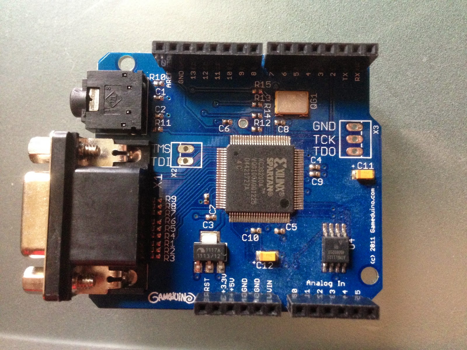
The Gameduino is a shield you can stack on top of the Arduino to get both a VGA monitor and stereo sound output. http://excamera.com/sphinx/gameduino/

Specs of the Gameduino
  • Video output is 400x300 pixels in 512 colors
  • All color processed internally at 15-bit precision
  • Compatible with any standard VGA monitor (800x600 @ 72Hz)
  • Background Graphics
    • 512x512 pixel character background
    • 256 characters, each with independent 4 color palette
    • Pixel-smooth X-Y wraparound scroll
  • Foreground Graphics
    • Each sprite is 16x16 pixels with per-pixel transparency
    • Each sprite can use 256, 16 or 4 colors
    • Four-way rotate and flip
    • 96 sprites per scan-line, 1536 texels per line
    • Pixel-perfect sprite collision detection
  • Audio output is a stereo 12-bit frequency synthesizer
    • 64 independent voices 10-8000 Hz
    • Per-voice sine wave or white noise
    • Sample playback channel
Sounds like the perfect match for my retro computer!

For the features I have planned, I need access to nearly all of the GPIO pins. Also, the Gameduino is designed to sit on top of an Arduino Uno, but the Mega2560 has different locations for its SPI pins. So rather than mount the Gameduino on top of the Arduino, I used jumper wires to connect only the pins that are required.


Jumper connections from Gameduino to Arduino Mega:
Pin 9 to Pin 9 (SS)
Pin 11 to Pin 51 (MOSI)
Pin 12 to Pin 50 (MISO)
Pin 13 to Pin 52 (SCK)
3.3V to 3.3V
5V to 5V
GND to GND

The Gameduino comes with an impressive Asteroids game with great graphics and sound. I temporarily wired up a few buttons to be able to play it. The example Asteroids game really gave me motivation to have gamepad style joysticks connected to the computer. Those are coming soon...