Showing posts with label joystick. Show all posts

Saturday, January 3, 2015

Arduino Retro Computer: Second Joystick

I've been able to build and wire up my second joystick!


Learning some lessons from the first version, I did redesign the lid so it fits better into the case. Rather than the prongs in the corners, the lid now has 4 tabs along the top and bottom of the joystick. I can drill holes through the joystick case and into the tabs to add a set screw to keep the lid in position (in the picture above you can see a set screw at the top left and bottom right of each controller).


The guts of the two controllers...


I printed a new lid for the first joystick as well so they're the same. The wiring inside the two controllers are identical. I did change the pin layout at the Arduino for joystick #1 so it would be grouped with joystick #2. My new pin layout:

const int Joystick1SelectPin = 40;
const int Joystick1RightPin = 41;
const int Joystick1TopPin = 42;
const int Joystick1LeftPin = 43;
const int Joystick1BottomPin = 44;
const int Joystick1AnalogX = 0; // Analog 0
const int Joystick1AnalogY = 1; // Analog 1

const int Joystick2SelectPin = 45;
const int Joystick2RightPin = 46;
const int Joystick2TopPin = 47;
const int Joystick2LeftPin = 48;
const int Joystick2BottomPin = 49;
const int Joystick2AnalogX = 2; // Analog 2
const int Joystick2AnalogY = 3; // Analog 3


Initializing my joysticks with the Joystick Class (described in the previous post):

  joysticks[0].init(Joystick1SelectPin, Joystick1RightPin, Joystick1TopPin, 
                    Joystick1LeftPin, Joystick1BottomPin, Joystick1AnalogX, Joystick1AnalogY);
  joysticks[1].init(Joystick2SelectPin, Joystick2RightPin, Joystick2TopPin, 
                    Joystick2LeftPin, Joystick2BottomPin, Joystick2AnalogX, Joystick2AnalogY);

And of course someone became very interested while I was doing the final wiring.


Thursday, December 25, 2014

Arduino Retro Computer: Joystick Interface

The joystick itself contains no logic - it's just push buttons and potentiometers. The brains of the input reside in the Arduino.

Some very good references on how to read analog and digital input on the Arduino:

http://arduino.cc/en/Tutorial/ReadAnalogVoltage
http://arduino.cc/en/tutorial/button
http://arduino.cc/en/Reference/Constants

Basically, we can't just wire from 5V through a push button then to the data input pin; we must use a pull-up (or pull-down) resistor. The critical piece for the push buttons from those references is as follows: "If you have your pin configured as an INPUT, and are reading a switch, when the switch is in the open state the input pin will be "floating", resulting in unpredictable results. In order to assure a proper reading when the switch is open, a pull-up or pull-down resistor must be used. The purpose of this resistor is to pull the pin to a known state when the switch is open. A 10 K ohm resistor is usually chosen, as it is a low enough value to reliably prevent a floating input, and at the same time a high enough value to not not draw too much current when the switch is closed."

Hardware

9-Position Female D-Sub Connector (Radio Shack #276-1538)
5x 10k Ohm Resistor
Breadboard

Wiring

The wiring for the select button is different than the 4 push buttons. The Joystick Breakout Board shorts Select (S1) to GND when the stick is pressed in. To read this, Select is wired with a pull-up resistor while the others are with pull-down.

Wiring Schematic:

Created with http://www.digikey.com/schemeit

The pin layout for the serial cable is as follows:

#1 S1 (Stick Select Button)
#2 S2 (Right Button)
#3 S3 (Top Button)
#4 S4 (Left Button)
#5 S5 (Bottom Button)
#6 Vcc
#7 Analog Xout
#8 Analog Yout
#9 GND


Code

I created a Joystick Class in my operating system code to ease in interfacing:
class JoystickModel
{
  private:
  int buttonPinSelect;
  int buttonPinRight;
  int buttonPinTop;
  int buttonPinLeft;
  int buttonPinBottom;
  int analogPinX;
  int analogPinY;

  public:
  bool init(int newButtonPinSelect, int newButtonPinRight, int newButtonPinTop, int newButtonPinLeft, int newButtonPinBottom,
            int newAnalogPinX, int newAnalogPinY)
  {
    buttonPinSelect = newButtonPinSelect;
    buttonPinRight = newButtonPinRight;
    buttonPinTop = newButtonPinTop;
    buttonPinLeft = newButtonPinLeft;
    buttonPinBottom = newButtonPinBottom;
    
    pinMode(buttonPinSelect, INPUT);
    pinMode(buttonPinRight, INPUT);
    pinMode(buttonPinTop, INPUT);
    pinMode(buttonPinLeft, INPUT);
    pinMode(buttonPinBottom, INPUT);

    analogPinX = newAnalogPinX;
    analogPinY = newAnalogPinY;
       
    return true;
  }
  
  bool selectPressed()
  {
    // Returns true if button is pressed.
    // Select button uses LOW because the joystick breakout shorts to ground with select.
    return (digitalRead(buttonPinSelect) == LOW);
  }
  
  bool leftPressed()
  {
    // Returns true if button is pressed.
    return (digitalRead(buttonPinLeft) == HIGH);
  }
  
  bool topPressed()
  {
    // Returns true if button is pressed.
    return (digitalRead(buttonPinTop) == HIGH);
  }
  
  bool rightPressed()
  {
    // Returns true if button is pressed.
    return (digitalRead(buttonPinRight) == HIGH);
  }
  
  bool bottomPressed()
  {
    // Returns true if button is pressed.
    return (digitalRead(buttonPinBottom) == HIGH);
  }
  
  float analogX()
  {
    // Returns position of stick between -1 and 1.
    // Take - as X potentiometer is mounted reversed on controller.
    return -(((float)analogRead(analogPinX) / 512.0) - 1.0);
  }
  
  float analogY()
  {
    // Returns position of stick between -1 and 1.
    // Take - as Y potentiometer is mounted reversed on controller.
    return -(((float)analogRead(analogPinY) / 512.0) - 1.0);
  }
};

Global:
const int Joystick1SelectPin = 3;
const int Joystick1RightPin = 4;
const int Joystick1TopPin = 5;
const int Joystick1LeftPin = 6;
const int Joystick1BottomPin = 7;
const int Joystick1AnalogX = 0;
const int Joystick1AnalogY = 1;

const byte numberOfJoysticks = 2;
JoystickModel joysticks[numberOfJoysticks];

Inside setup():
  joysticks[0].init(Joystick1SelectPin, Joystick1RightPin, Joystick1TopPin, 
                    Joystick1LeftPin, Joystick1BottomPin, Joystick1AnalogX, Joystick1AnalogY);

Inside loop():
  float analogX = joysticks[0].analogX();
  float analogY = joysticks[0].analogY();
  char analogXString[10];
  char analogYString[10];
  dtostrf(analogX, 5, 3, analogXString);
  dtostrf(analogY, 5, 3, analogYString);
  Serial.print("Analog X: ");
  Serial.print(analogXString);
  Serial.print(" Analog Y: ");
  Serial.print(analogYString);

  if (joysticks[0].selectPressed())
  {
    Serial.print(" Select Pressed");
  }
  if (joysticks[0].rightPressed())
  {
    Serial.print(" Right Pressed");
  }
  if (joysticks[0].topPressed())
  {
    Serial.print(" Top Pressed");
  }
  if (joysticks[0].leftPressed())
  {
    Serial.print(" Left Pressed");
  }
  if (joysticks[0].bottomPressed())
  {
    Serial.print(" Bottom Pressed");
  }
  Serial.println("");


Output from the console:


Asteroids + Controller


I wanted to play the Asteroids game with my new controller, so I made the following changes to the game code to get it to work:

Replaced controller_init() with:
static void controller_init()
{
  // Configure input pins with internal pullups
  pinMode(6, INPUT);
  pinMode(7, INPUT);
}

Replaced controller_sense() with:
static byte controller_sense(uint16_t clock)
{
  byte r = 0;
  if (digitalRead(6))
  {
    r |= CONTROL_UP;
  }
  if (digitalRead(7))
  {
    r |= CONTROL_DOWN;
  }
  return r;
}

In static void handle_player(byte i, byte state, uint16_t clock), there is a line:
    char rotate = (512 - analogRead(0)) / 400;
Since my stick is reversed, I just had to make that negative:
    char rotate = -(512 - analogRead(0)) / 400;


Copyright (c) 2015 Clinton Kam
Permission is hereby granted, free of charge, to any person obtaining a copy of this software and associated documentation files (the "Software"), to deal in the Software without restriction, including without limitation the rights to use, copy, modify, merge, publish, distribute, sublicense, and/or sell copies of the Software, and to permit persons to whom the Software is furnished to do so, subject to the following conditions:
The above copyright notice and this permission notice shall be included in all copies or substantial portions of the Software.
THE SOFTWARE IS PROVIDED "AS IS", WITHOUT WARRANTY OF ANY KIND, EXPRESS OR IMPLIED, INCLUDING BUT NOT LIMITED TO THE WARRANTIES OF MERCHANTABILITY, FITNESS FOR A PARTICULAR PURPOSE AND NONINFRINGEMENT. IN NO EVENT SHALL THE AUTHORS OR COPYRIGHT HOLDERS BE LIABLE FOR ANY CLAIM, DAMAGES OR OTHER LIABILITY, WHETHER IN AN ACTION OF CONTRACT, TORT OR OTHERWISE, ARISING FROM, OUT OF OR IN CONNECTION WITH THE SOFTWARE OR THE USE OR OTHER DEALINGS IN THE SOFTWARE.

Saturday, December 20, 2014

Arduino Retro Computer: Joystick Construction

Common in the older connect-to-your-television computers were joysticks. After all, those computers were really for playing games (yes, they were advertised as "educational" or for "work", but my TI-99/4A has built in joystick ports for a reason). The Asteroids game included in the Gameduino definitely convinced me I needed joysticks. Yes I could retrofit a classic Nintendo controller, or... I could build one from scratch.

Hardware:

Dual Printed Circuit Board (Radio Shack #276-148)
Round Tact Buttons (Adafruit #1009)
Joystick Breakout Board (Adafruit #512)
9-Position Male D-Sub Connector (Radio Shack #276-1537)
6' Serial Cable (Radio Shack #26-1402)
#4-40 x 3/8" Bolts
#4-40 x 1/2" Bolts
#6 Washers

Creating the Case:

I used Sketch Up to create a case. The case includes extruded mounts for the two boards and an opening for the serial connector:


The lid for the case:


The extrusions at the 4 corners of the lid are so it doesn't have any play room to rotate or slide around the case. The extrusion in the middle is so I can put a set screw to secure the lid onto the case. It is opposite of the serial cable connection.

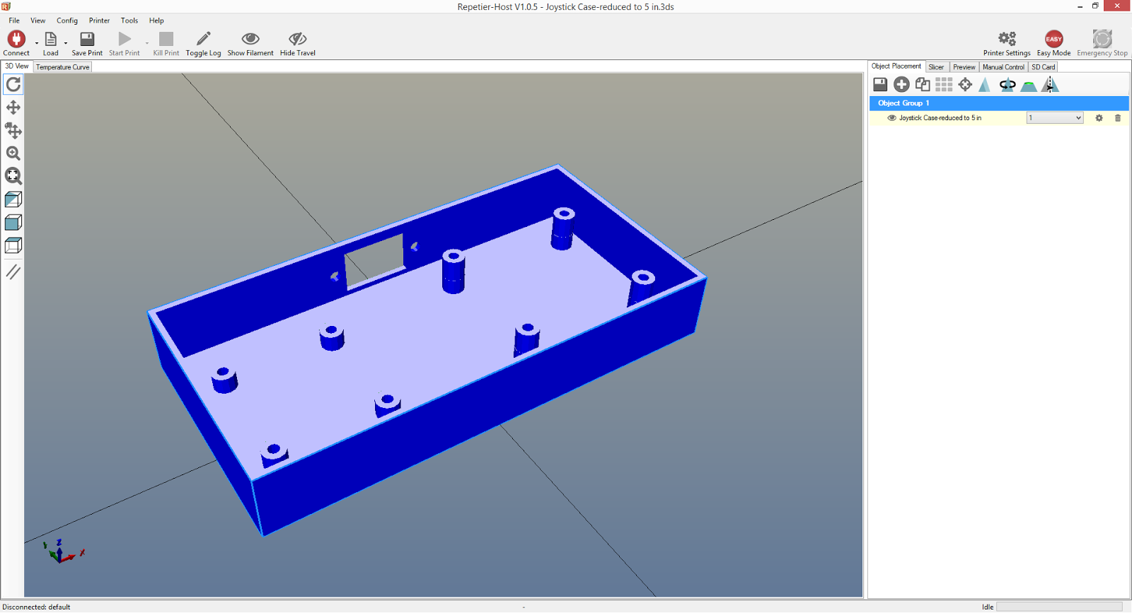
I used Repetier / Slic3r to create the G-code of my case:


3 hours 4 minutes later I had my printed case!


Well, one more hour for the lid.


(There are all sorts of tips and tricks out there on how to get the first layer to stick to the print surface. I've found double sided tape to work very well. It's cheap and it easily comes off the finished part.)

I basically had to monitor the print for the entire 4 hours, someone is very interested in the printer...


Wiring:

The brains of the joystick will be with the Arduino. The joystick itself is basically just a collection of buttons and potentiometers wired to a serial cable.

Wiring Schematic:


The pin layout for the serial cable is as follows:

#1 S1 (Stick Select Button)
#2 S2 (Right Button)
#3 S3 (Top Button)
#4 S4 (Left Button)
#5 S5 (Bottom Button)
#6 Vcc
#7 Analog Xout
#8 Analog Yout
#9 GND

I wired the Vcc from the D-Sub connector to the button board - then I jumped the Vcc from the button board to the analog stick board. This helped keep the wire area around the connector clean and simple. Photo of the back so that makes sense...


In the photo above you can see the Vcc long bare wire that makes connections across all the buttons.

The final product!

Lid off:


Lid on:


I was expecting to needs nuts for the mounting bolts, so I designed the case with the holes going all the way through. However I've found the #4 bolts fit snugly in the 1/8" diameter holes and no nuts were necessary. I did need a few washers for the bolts on the analog stick board as the 3/8" length bolts were too long and would protrude out (I suppose I could have found shorter bolts or dremeled the bolts in half, but washers were easier.)


The bottom turned out nice and flat.

Lessons Learned:

The case came out pretty well, but there are a couple items that could be improved upon:

#1 Probably the most significant change needed is the analog stick. When in the neutral position it looks great, but as the stick tilts you can see behind the analog's cone cover. To prevent that, I need to have the overall case be thicker so I can put the lid higher over the analog stick. With the lid higher, I'd be able to use a smaller hole that closes around the analog stick's cone cover. Then as the stick tilts you wouldn't be able to look inside the case. I'd rather not have the controller be any bulkier though and really that's getting pretty nit-picky. For my purposes it's not a big deal.

#2 I could have gone a bit fancier with how the lid fits onto the case. Maybe cut some gaps in the case that the lid notches / snaps into? I'll think about it. The lid fits a bit tight right now. I need to give the lid's extrusions probably 1/16" or 1/32" clearance from the edges of the case so it fits in better and doesn't try to bow out.

This is just the first joystick; I've purchased enough parts to build a second for multiplayer. I'll give this first one some use and think about more tweaks before I construct the second.

Next up, the joystick wiring at the Arduino!